Sample source
Browse the full sample on GitHub: raytrace_tutorial/22_partition_tlas
22 Partitioned TLAS (PTLAS) - Tutorial
What is a PTLAS, and what is it for?
Ray tracing a dynamic scene means keeping a top-level acceleration structure (TLAS) in sync with
the instances every frame. With an ordinary VK_KHR_acceleration_structure TLAS that is an
all-or-nothing job: the TLAS is a flat array of instances, so to move anything you hand the driver
the whole instance array and (re)build. For a few hundred instances that is fine. For the scenes
this extension targets — cities, crowds, forests with hundreds of thousands to millions of
instances, most of which are not moving on any given frame — reprocessing everything every frame is
pure waste.
A Partitioned TLAS (PTLAS), from VK_NV_partitioned_acceleration_structure, is built for exactly
that case. Two ideas make it work:
- Instances live in indexable, retained slots. You build the structure once, then update it
in place (
src == dst) from a small list of operations. Crucially, an in-place build keeps every instance you do not re-submit — so a per-frame update contains only what changed. The cost scales with the size of your delta, not with the size of the scene. - Instances are grouped into partitions. A whole partition of instances can be moved with a
single record (
WRITE_PARTITION_TRANSLATION), and partitions give the driver a natural unit for streaming regions in and out.
Key Takeaway: A PTLAS is one structure over many partitions, referenced by device address (not a
VkAccelerationStructureKHRhandle). You build it once, then rebuild it in place with a tiny op list that touches only what changed; everything else is retained for free. A classic TLAS has no equivalent — to move anything it reprocesses all of its instances.
How this sample shows the advantage
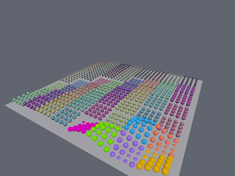
To make "only pay for what changed" visible, the sample drives updates by camera distance.
A 32×32 grid of sphere instances is tiled into 8×8 spatial partitions (16 instances each), plus
a ground plane in the special global partition. Two radii around the camera carve the grid into
three zones, and each zone gets a different operation, a different cost, and a different level of
detail (LOD):
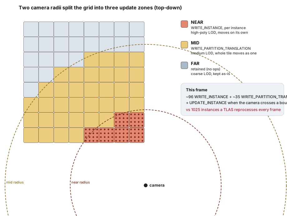
| Zone | Distance from camera | Operation each frame | LOD (BLAS) | What you see |
|---|---|---|---|---|
| NEAR | inside the near radius | WRITE_INSTANCE per instance |
high-poly sphere | each sphere ripples on its own |
| MID | between the two radii | WRITE_PARTITION_TRANSLATION per partition |
medium sphere | the whole 16-sphere tile rocks as one |
| FAR | beyond the mid radius | nothing — retained | coarse sphere | sits perfectly still, at zero cost |
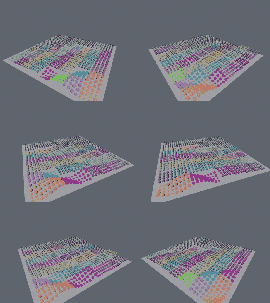
When a partition crosses the MID↔FAR boundary as the camera moves, its instances are re-pointed at
the new zone's BLAS with UPDATE_INSTANCE — a cheap swap of geometry with no transform change.
(Crossings into the NEAR zone need no separate op: those instances are re-specified by WRITE_INSTANCE
anyway, which already carries the BLAS.) So the sample exercises all three core PTLAS operations, each
tied to a zone.
Move the camera and the zones follow it. The Settings panel reports the exact op counts: a
typical frame submits roughly ~96 WRITE_INSTANCE + ~35 WRITE_PARTITION_TRANSLATION records
(plus a burst of UPDATE_INSTANCE whenever a partition crosses the MID↔FAR boundary) — versus the
1025 instances a TLAS would reprocess to move anything at all. Everything in the FAR zone costs nothing,
because the src == dst build retains it.
The LOD makes the zones unmistakable — smooth spheres near, faceted ones far — and the shader adds a gentle fog of distance (NEAR vivid, FAR muted) using the same test the update logic uses, so the bright, detailed foreground is precisely the region paying the per-instance cost.
The idea: build once, update with a delta
An ordinary TLAS is rebuilt from the full instance array; a PTLAS is rebuilt in place from a small list of operations applied against the structure that already exists:
(only what changed)"] --> b2["build in place
src == dst"] --> b3["PTLAS"] b3 -. retained instances .-> b2 end
Partitions and the global partition
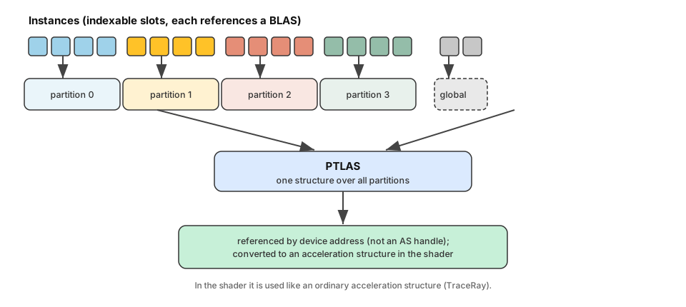
Every instance is assigned to a partition through its partitionIndex. A partition is meant to
hold instances that move or stream together (here, one 4×4 tile of the grid), so the driver can
treat them as a unit — that is what lets a single translation record move all 16 at once. One special
bucket, the global partition (VK_PARTITIONED_ACCELERATION_STRUCTURE_PARTITION_INDEX_GLOBAL_NV),
holds instances that are not localized to a region; this sample puts the world-spanning ground
plane there. Capacity is declared up front, and partitionCount must not exceed the device's
maxPartitionCount.
Building the PTLAS
Sizing is queried from a capacity descriptor (no instance data needed yet). The translation feature
is turned on by chaining a flags struct — without it, WRITE_PARTITION_TRANSLATION is not allowed:
Modified: 22_partition_tlas.cpp — allocatePtlasBuffers()
m_input = VkPartitionedAccelerationStructureInstancesInputNV{
    .sType                             = VK_STRUCTURE_TYPE_PARTITIONED_ACCELERATION_STRUCTURE_INSTANCES_INPUT_NV,
    .pNext                             = &m_inputFlags,   // enablePartitionTranslation = VK_TRUE
    .flags                             = VK_BUILD_ACCELERATION_STRUCTURE_PREFER_FAST_TRACE_BIT_KHR,
    .instanceCount                     = kNumInstances,       // 1024 spheres + 1 plane
    .maxInstancePerPartitionCount      = kTile * kTile,       // 16
    .partitionCount                    = kPartitions,         // 64
    .maxInstanceInGlobalPartitionCount = 1,                   // the ground plane
};
vkGetPartitionedAccelerationStructuresBuildSizesNV(device, &m_input, &sizes);
Each instance is fully defined by a WRITE_INSTANCE record. Note it carries a stable instanceIndex
(the slot we re-specify on later updates) and a partitionIndex, and that we stash the partition into
instanceID so the shader can read it back to colorize:
Modified: 22_partition_tlas.cpp — makeInstance()
VkPartitionedAccelerationStructureWriteInstanceDataNV w{};
w.transform             = nvvk::toTransformMatrixKHR(instanceTransform(i));  // grid cell (+ animated Y)
w.instanceID            = m_instancePartition[i];  // -> InstanceID() in the shader (color by partition)
w.instanceMask          = 0xFF;
w.instanceFlags         = VK_PARTITIONED_ACCELERATION_STRUCTURE_INSTANCE_FLAG_TRIANGLE_FACING_CULL_DISABLE_BIT_NV;
w.instanceIndex         = i;                        // stable slot, targeted by later WRITE_INSTANCE
w.partitionIndex        = partition;                // or ..._PARTITION_INDEX_GLOBAL_NV for the plane
w.accelerationStructure = m_asBuilder.blasSet[meshIndex].address;  // BLAS by device address
The build is command-list driven. srcInfos points at an array of operation commands, each of
which points at its own array of records; srcInfosCount gives the number of commands. The initial
build submits a single WRITE_INSTANCE command with src == 0 (from scratch); every later frame
reuses the same call with src == dst:
Modified: 22_partition_tlas.cpp — recordBuild()
VkBuildPartitionedAccelerationStructureInfoNV buildInfo{
    .sType                        = VK_STRUCTURE_TYPE_BUILD_PARTITIONED_ACCELERATION_STRUCTURE_INFO_NV,
    .input                        = m_input,
    .srcAccelerationStructureData = update ? m_ptlasAddr : 0,   // 0 = from scratch; else in place
    .dstAccelerationStructureData = m_ptlasAddr,
    .scratchData                  = fr.scratch.address,
    .srcInfos                     = fr.ops.address,             // array of operation commands
    .srcInfosCount                = fr.opsCount.address,        // how many commands
};
vkCmdBuildPartitionedAccelerationStructuresNV(cmd, &buildInfo);
Binding the PTLAS
A PTLAS is not a VkAccelerationStructureKHR handle — the result lives in an app-owned buffer and
is referenced by device address. The simplest, most portable way to trace against it (and the way
the vk_forest_ray_tracing reference does it) is to pass that address to the shader and convert it to
an acceleration structure there:
Modified: 22_partition_tlas.cpp — raytraceScene()
m_pushValues.tlasAddress = m_ptlasAddr; // the PTLAS buffer's device address, into the push constant
In the shader the address is turned into an acceleration structure and traced like any other:
Modified: partition_tlas.slang
RaytracingAccelerationStructure topLevelAS = RaytracingAccelerationStructure(pushConst.tlasAddress);
TraceRay(topLevelAS, RAY_FLAG_NONE, 0xFF, 0, 0, 0, ray, payload);
The extension also defines a descriptor type,
VK_DESCRIPTOR_TYPE_PARTITIONED_ACCELERATION_STRUCTURE_NV, but a standard acceleration-structure shader variable compiles toOpTypeAccelerationStructureKHR, which the validation layers pair only withVK_DESCRIPTOR_TYPE_ACCELERATION_STRUCTURE_KHR. Binding by device address avoids that mismatch and traces a regular TLAS and a PTLAS with the exact same shader.
The three zones in one frame (the payoff)
This is where the advantage becomes concrete. Each frame we classify every partition by its distance to the camera and build a delta — nothing more. Both lists are tracked against the previous frame, so a partition that crosses a zone boundary is settled exactly once, and a fully static frame emits zero operations.
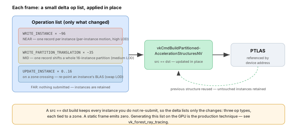
NEAR → WRITE_INSTANCE per instance. Inside the near radius, every sphere is re-specified with
its own animated transform, so it can move independently:
Modified: 22_partition_tlas.cpp — fillBuildOps()
const int  p      = m_instancePartition[i];
const Zone zone   = zoneOf(p, camXZ);
const bool isNear = (zone == eNear);
if(m_initialBuilt && !isNear && m_wasNear[p] == 0)
  continue;                                           // retained -> no op
float yOff = 0.0f;
if(isNear)
{
  const float phase = 0.5f * float((i % kGridN) + (i / kGridN));  // per-instance -> a travelling ripple
  yOff              = m_instBob * std::sin(m_time * m_bobSpeed + phase);
}
const uint32_t mesh = lodMesh(zone);                  // high / medium / coarse BLAS for this zone
wi[numInst++]       = makeInstance(i, yOff, mesh);    // WRITE_INSTANCE record (transform + LOD BLAS)
MID → WRITE_PARTITION_TRANSLATION per partition. Between the two radii, each partition is
shifted rigidly by one record — 16 instances moved for the price of one:
const float phase = 0.7f * float((p % kPartAxis) + (p / kPartAxis));
const float y     = (zoneOf(p, camXZ) == eMid) ? (m_partBob * std::sin(m_time * m_bobSpeed + phase)) : 0.0f;
if(!m_initialBuilt || std::fabs(y - m_prevPartY[p]) < 1e-4f)
  continue;                                           // first build, or unchanged -> no op
m_prevPartY[p]                       = y;
pt[numMoved].partitionIndex          = p;
pt[numMoved].partitionTranslation[1] = y;             // rigid Y offset for the whole partition
FAR → nothing. Partitions beyond the mid radius are never mentioned; the src == dst build keeps
them.
Crossing a boundary → UPDATE_INSTANCE. When the camera moves, a partition can slip from MID to
FAR (or back). Its transform is retained, but its LOD must change — so we re-point its 16 instances
at the new zone's BLAS with UPDATE_INSTANCE, which carries only the instance index and an
acceleration-structure address:
const Zone zone           = zoneOf(p, camXZ);
const bool touchedByWrite = (zone == eNear) || (m_wasNear[p] != 0);
if(touchedByWrite || zone == m_prevZone[p])
  continue;                                                 // handled by WRITE_INSTANCE, or LOD unchanged
const VkDeviceAddress blas = m_asBuilder.blasSet[lodMesh(zone)].address;  // the new LOD
for(int local = 0; local < kTile * kTile; local++)          // the partition's 16 instances
{
  ui[numUpdate].instanceIndex         = partitionInstance(p, local);
  ui[numUpdate].accelerationStructure = blas;               // swap geometry, keep the transform
  numUpdate++;
}
(NEAR crossings need no separate op — the WRITE_INSTANCE path already sets each instance's BLAS; and
the UPDATE_INSTANCE pass is skipped entirely on the first build.) Whichever lists are non-empty are
packed into the ops buffer; if all are empty, no build is recorded at all.
Reading the partition — and its zone — in the shader
Because we wrote the partition index into each instance's instanceID, the closest-hit shader reads
it back with InstanceID() and colorizes — the same "color by ID" idea as the clusters chapter (21),
here applied to partitions. Every grid instance is a sphere centered at its object origin, so the
object-space hit position is the surface normal — no vertex or normal buffers are needed:
Modified: partition_tlas.slang
uint id = InstanceID();                               // the partition we stored, or PT_GROUND_ID
if(id == PT_GROUND_ID) { normal = float3(0,1,0); base = float3(0.35, 0.35, 0.38); }   // flat ground plane
else {
  float3 objPos = ObjectRayOrigin() + RayTCurrent() * ObjectRayDirection();
  normal        = normalize(mul((float3x3)ObjectToWorld4x3(), objPos));   // sphere normal, no buffers
  base          = applyZone(partitionColor(id), id);   // partition hue, re-shaded by update zone
}
To make the three zones easy to tell apart, the shader also shades each instance by its zone. It
recomputes the partition's center and its distance to the camera — using the same radii the host
uses — and applies a "fog of distance": NEAR stays vivid and bright, MID is dimmer, FAR is dark and
desaturated. Because it is the identical test, the vivid foreground spheres are exactly the instances
being re-specified with WRITE_INSTANCE this frame:
Modified: partition_tlas.slang — applyZone()
// partition center (same formula as the host), then its distance to the camera:
float d = length(partitionCenterXZ - pushConst.cameraXZ);
float saturation, brightness;
if(d < pushConst.nearRadius)     { saturation = 1.50; brightness = 1.00; }  // NEAR — vivid
else if(d < pushConst.midRadius) { saturation = 0.50; brightness = 0.50; }  // MID  — dimmer
else                             { saturation = 0.15; brightness = 0.32; }  // FAR  — dark, desaturated
float lum = dot(base, float3(0.299, 0.587, 0.114));
return lerp(float3(lum), base, saturation) * brightness;
The camera position and the two radii travel to the shader in the push constant, refreshed every frame, so the shaded zones track the camera exactly as the update zones do.
Design note: where the op list comes from
This sample writes its op list on the CPU into host-mapped buffers, then the build (recorded on
the frame command buffer) reads them directly. That is the clearest way to see the op model — the
fillBuildOps loop maps one-to-one onto the API structs — but it is a deliberate teaching choice with
a trade-off worth understanding:
- CPU-written, host-mapped (this sample). No staging, no copy, no compute pass; trivial to read and debug; excellent on integrated/UMA GPUs. But the CPU touches instances every frame (it does not scale to millions), host-visible reads are slower for the GPU on discrete cards, and because the CPU writes what the GPU reads, the argument buffers must be ring-buffered per frame-in-flight.
- GPU-driven, device-local (production). A compute shader evaluates visibility/LOD/animation for
the whole scene and writes the op list — and the op count — into device-local buffers; the CPU
issues one indirect build and never iterates instances. The API takes
srcInfosandsrcInfosCountby device address precisely to allow this. More plumbing (a compute pass plus barriers), but it is the only thing that scales. This is whatvk_forest_ray_tracingdoes.
In short: host-mapped is simple, immediate, and CPU-bound; GPU-driven is more code but scales.
Technical details
- Extension / feature:
VK_NV_partitioned_acceleration_structureon top of the usual RT stack. The device is queried forpartitionedAccelerationStructure; if absent, the sample still runs and says so in the UI.partitionCountis enforced againstmaxPartitionCountat runtime. - Synchronization: the update is recorded on the frame command buffer, wrapped in a full
memory barrier before and after (acceleration-structure, shader, transfer, and indirect-command
access) so the trace never reads a partially-built structure. The scratch and host-mapped argument
buffers are ring-buffered by
getFrameCycleSize(). - No RT-pipeline pNext is required, and the ray tracing descriptor set holds only the output image — the PTLAS is passed by device address, not bound as a descriptor.
- Framework fit: derives from
RtBaselike the other chapters.RtBase::createBottomLevelASbuilds the four BLAS (three sphere LODs + the plane); this chapter overridescreateTopLevelAS(the PTLAS build),onRender(the per-frame delta),createRaytraceDescriptorLayout,createRayTracingPipeline, andraytraceScene. The G-buffer, tonemapper, camera, and headless screenshot are reused unchanged.
Usage instructions
Orbit the grid and drive the demo from Settings → Partitioned TLAS:
- Play / the time slider — run the timeline, or pause and scrub it.
- Near radius / Mid radius — resize the two zones; watch the
WRITE_INSTANCEandWRITE_PARTITION_TRANSLATIONcounts follow. Orbit the camera (mouse-drag) and the zones move with it — instances crossing a boundary swap LOD and spike theUPDATE_INSTANCEcount. - Instance bob / Partition bob — the per-instance (NEAR) and per-partition (MID) amplitudes.
- Bob speed — animation rate.
- Light direction — orbit the diffuse light.
Command line (also used to generate this page's figures):
---time <sec> sets the timeline position (deterministic capture).
- --play <0|1> advances the timeline automatically.
- --azimuth <deg> sets the initial camera orbit angle.
- --orbit <0|1> slowly orbits the camera (demonstrates the UPDATE_INSTANCE LOD swaps).
- --frames <n> number of frames to render in headless mode.
- --headless renders and writes a screenshot next to the executable.
Summary
A PTLAS groups instances into partitions and is referenced by device address. You build it once with
WRITE_INSTANCE, then rebuild it in place (src == dst) with a small op list — WRITE_INSTANCE
to re-specify individual instances, WRITE_PARTITION_TRANSLATION to move whole partitions, and
UPDATE_INSTANCE to swap an instance's BLAS (here, its LOD) — while everything you don't mention is
retained. This chapter makes the payoff visible by keying all three operations to camera distance:
per-instance updates + high LOD NEAR, per-partition updates + medium LOD in the MID ring, and zero cost
+ coarse LOD FAR away, with UPDATE_INSTANCE swapping LOD as instances cross a boundary — so per-frame
work tracks what changed, not the size of the scene.
Next steps
- See the production-scale use of PTLAS — spatial partitions driven by a zone system, GPU-generated
op lists, streaming, and combined with cluster geometry — in the
vk_forest_ray_tracingsample. - Combine PTLAS with the clusters chapter (21): partitions of cluster-based instances for a large, dynamic, LOD'd world.